
Pros and Cons of Rigid-Flex PCBs
Rigid-flex circuit boards provide durability and space efficiency in consumer electronics. The PCB design is a mix of rigid and flexible materials that can be folded or twisted to fit the product’s desired shape. They offer more durability than traditional printed circuit boards, and can even withstand the vibration and shock that is common in consumer electronic products. They can also be used in more extreme environmental conditions, such as aerospace or medical applications.
rigid-flex printed circuit board are made of a combination of rigid and flexible substrates, with the rigid parts being used to carry components and the flex parts serving as interconnection paths. They can be designed in a variety of shapes, and are often used in smaller devices that require more structural integrity than larger devices. Rigid-flex circuits can also be integrated with a variety of components and technologies, including surface mount technology (SMT) and through-hole technology (THT).
The combining of rigid and flexible components makes the board stronger and more durable, and allows it to adapt to changes in environment, such as bending or twisting. However, the combination of rigid and flex components can also make the board harder to manufacture. For example, the manufacturing processes for rigid-flex circuits are different from those of rigid boards, and there are additional tests that must be performed. Additionally, the flex components have different thermal expansion properties from the rigid materials, which can lead to signal degradation and electromagnetic interference (EMI) problems if not taken into account during the design phase.
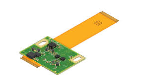
What Are the Pros and Cons of Rigid-Flex PCBs?
To overcome these challenges, it is important to work with a PCB fabrication partner that has experience in flex and rigid-flex designs. The partner should be able to provide recommendations early in the design process, and ensure that the rigid and flex parts are properly aligned. In addition, the partner should be able to recommend materials that will best meet the requirements of the application.
Another key consideration is the choice of connectors. Poor connector placement can cause mechanical stress and failure, especially in the flex sections of the board. The flex section must also be insulated from the rigid sections, to avoid interference between signals. It is also important to consider the thickness of the flex circuits, as the thinner ones will be more susceptible to damage from environmental factors.
Lastly, it is important to choose a layout that will allow the rigid and flex sections of the board to be joined together in the assembly stage. This is critical to maintaining signal integrity and preventing mechanical stress on the connections. A good way to do this is to use a coverlay, which is a layer of insulating material on the outside of the flex substack that can be punched through to access the signal layers. A bondpile is a similar layer, but is used on the inner stripline layers to glue two flex cores together.
A combination of flexible and rigid materials, plated through holes and high-density interconnect (HDI) is the most common construction for a rigid-flex circuit. However, there are other options available depending on the design and assembly process required. For example, it is possible to add stiffeners, which are rigid materials (typically FR4) added to specific areas of the flex substack, to increase rigidity and stability.

